Overview of Transfer Switch Wiring Diagrams
Transfer switch wiring diagrams guide installers through connecting a backup source to a home’s main panel. During heightened hurricane and wildfire risks, accurate diagrams ensure generators feed safely, preventing back‑feed and protecting utility workers. Proper labeling and grounding complete the net now
Safety Precautions Before Wiring
Before wiring a transfer switch, observe these safety steps:
- Disconnect Utility: Turn off the main breaker, lock‑out/tag‑out the panel, and verify zero voltage.
- Grounding: Bond the switch and generator frame to the building’s grounding electrode; check continuity.
- PPE: Wear insulated gloves, safety glasses, flame‑resistant clothing, and keep an electrical fire extinguisher nearby.
- Inspect Parts: Replace any damaged conductors, connectors, or fuses.
- Load Check: Ensure the generator can supply the connected load; avoid overloading.
- Follow Diagram: Wire strictly per the manufacturer’s schematic; do not improvise.
- Test: Perform a no‑load test to confirm proper operation and isolation.
These precautions protect personnel, equipment, and prevent costly downtime.
When working with transfer switches, always verify the isolation of the main panel before connecting the generator. Use a lock‑out device to prevent re‑engagement of the utility feed. Keep the wiring area clean and free of combustible materials. Finally, document the wiring configuration for future reference!!.
Key Components in a Transfer Switch Diagram
Understanding each element in a transfer‑switch schematic is essential for accurate installation and troubleshooting. Below is a concise inventory of the most common parts you’ll encounter in a manual wiring diagram, along with brief notes on their function and typical placement.
- Main Panel Bus Bars – The central bus that distributes power to the home’s circuits. In the diagram they are shown as a thick horizontal line with labeled circuit numbers, indicating where each branch connects.
- Transfer Switch Contacts – A set of double‑pole, normally‑open contacts that physically disconnect the utility feed and connect the generator. They are depicted as a pair of vertical lines with a switch symbol between them, and the diagram will note the contact rating (e.g., 240 V, 200 A).
- Generator Feed Cable – The insulated cable that carries power from the generator to the switch. The schematic indicates its gauge, length, and termination points, and often includes a note on the required ampacity per NEC tables.
- Grounding Electrode System – A grounding rod or plate connected to the switch frame. The diagram shows a ground symbol and a reference to the building’s grounding electrode, ensuring the system complies with NEC 250.30.
- Overcurrent Protection Devices – Circuit breakers or fuses protecting the transfer switch and associated conductors. They are shown as small boxes with rating labels, and the diagram will specify the type (thermal‑magnetic, GFCI, etc.).
- Isolation Switches – Often a manual or automatic lock‑out device that ensures the utility source is fully disconnected before generator power is applied. The schematic will show a toggle or latch symbol with a lock‑out tag reference.
- Labeling and Markings – Clear identification of line, load, and neutral conductors, as well as polarity indicators for the generator. The diagram uses color codes (black/red for hot, white for neutral, green/bare for ground) and phase labels (L1, L2, L3) where applicable.
- Neutral Bus – The common return path for all circuits. In a balanced system it is shown as a separate line parallel to the main bus, with a neutral bar symbol and a reference to the neutral ground jumper.
- Indicator Lights – LED or bulb symbols that show the status of the transfer switch (e.g., “Utility” vs. “Generator”). The diagram will note the wiring for these indicators and their power source.
- Compliance Symbols – NEC or UL markings that confirm the diagram meets code requirements. These symbols are placed near the schematic title and include reference numbers for the applicable code sections.

Additionally, pay attention to the color‑coding conventions: black or red for hot, white for neutral, green or bare for ground. The diagram will often annotate these colors next to each conductor line. In multi‑phase installations, you’ll see separate symbols for each phase (L1, L2, L3). Finally, note any special requirements such as a dedicated transfer line for critical loads or a separate bypass circuit for continuous operation.
When the generator is a standby unit, the diagram may include a “disconnect switch” that isolates the generator from the main panel when not in use. This is typically represented by a small toggle symbol. For portable generators, the schematic will show a “generator inlet” with a 120‑V or 240‑V receptacle, and a “generator transfer cable” that must be rated for the expected load. In all cases, the diagram should specify the required conductor size using the ampacity tables from the NEC.
Finally, the diagram often contains a “maintenance access” note, indicating where to place a lock‑out device or where to inspect the switch for corrosion. This ensures long‑term reliability and compliance with safety standards.

Types of Transfer Switches and Their Wiring Requirements
Manual, automatic, and portable switches differ in wiring. Manual requires a feed, grounding, and isolation. Automatic uses a relay and must meet NEC 705. Portable demands a 120/240 V inlet, proper conductor sizing, and a lock‑out tag.
Manual Transfer Switch Wiring Steps
Disconnect Utility Power: Turn off the main breaker and confirm zero voltage with a multimeter. This eliminates back‑feed risk during installation.
Install Transfer Switch: Mount the switch in the panel box, aligning its bus bars with the existing panel bus. Secure with the supplied mounting screws, ensuring no loose parts.
Calculate Load: Review the home’s 240‑V load to verify the generator’s capacity. Use the panel’s load schedule and the generator’s nameplate rating to confirm compatibility.
Connect Generator Feed: Run a dedicated 240‑V feeder from the generator inlet to the transfer switch. Use a 4‑wire cable (hot, hot, neutral, ground) sized per NEC 225.30.
Wire the Switch: Attach the generator feed to the “Generator” terminals and the house supply to the “House” terminals. Follow the manufacturer’s color‑coding guide, ensuring correct phase alignment.
Grounding: Connect the switch frame to the panel’s grounding bus with a copper strap. Verify continuity with a continuity tester and check for proper bonding.
Labeling: Mark all conductors with “GEN” or “HOUSE” tags. Use weather‑resistant labels and verify they remain legible after installation.
Verify Breaker Ratings: Ensure the transfer switch’s breaker rating matches or exceeds the panel’s main breaker. Replace any mismatched components before proceeding.
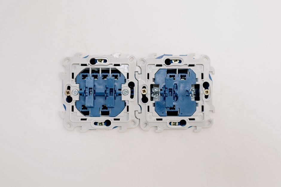
Test the System: With the generator running, switch the transfer switch to the generator position. Check that all circuits are energized, the main breaker stays off, and no nuisance tripping occurs.
Use a Transfer Switch Tester: Run a diagnostic test with a transfer switch tester to confirm proper isolation and correct polarity on all phases.
Final Inspection: Inspect all connections for tightness, no exposed conductors, and proper panel sealing. Verify that the panel cover is securely fastened.
Document Installation: Record the installation details in the maintenance log, noting dates, generator model, and any deviations from the standard procedure.
Automatic Transfer Switch Wiring Steps
Step 1: Disconnect the main breaker and verify zero voltage with a calibrated multimeter to eliminate back‑feed risk. Step 2: Mount the ATS in the panel enclosure, aligning its bus bars with the existing panel bus and securing it with the supplied mounting hardware. Step 3: Review the panel’s load schedule and the ATS’s rated capacity; confirm the generator’s output matches the ATS rating to avoid overload. Step 4: Run a dedicated 4‑wire feeder (hot, hot, neutral, ground) from the generator inlet to the ATS’s “Generator” terminals, sizing the cable per NEC 225.30 and terminating with crimped spade connectors. Step 5: Connect the ATS “House” terminals to the panel bus, ensuring correct phase sequence and using the manufacturer’s color‑coding diagram to avoid miswiring. Step 6: Bond the ATS frame to the panel’s grounding bus with a copper strap; verify continuity with a multimeter and eliminate any loose connections. Step 7: Install the ATS control circuitry by wiring the control relay or micro‑controller to the generator’s start/stop signals, following the manufacturer’s wiring diagram and ensuring proper isolation; Step 8: Label all conductors with “GEN” or “HOUSE” tags, securing them with weather‑resistant labels and verifying legibility after installation. Step 9: Perform a functional test: with the generator running, trigger the ATS to switch to the generator position; verify all circuits are energized, the main breaker remains off, and no nuisance tripping occurs. Step 10: Use an ATS diagnostic tool to confirm isolation, correct polarity, and proper breaker operation; record the test results in the maintenance log. Step 11: Inspect all connections for tightness, no exposed conductors, and proper panel sealing; ensure the panel cover is securely fastened. Step 12: Document the installation details—including dates, generator model, and any deviations from the standard procedure—in the final report to facilitate future maintenance and compliance audits.
Portable Generator Transfer Switch Wiring Steps
Step 1: Verify the portable generator’s output matches the rated capacity of the transfer switch and the circuit load. Use a calibrated clamp meter to confirm the generator’s voltage and frequency before connecting. Step 2: Mount the transfer switch in the panel enclosure, aligning its bus bars with the existing panel bus and securing it with the supplied mounting hardware. Step 3: Run a dedicated 4‑wire feeder (hot, hot, neutral, ground) from the generator inlet to the transfer switch’s “Generator” terminals, sizing the cable per NEC 225.30 and terminating with crimped spade connectors. Step 4: Connect the transfer switch “House” terminals to the panel bus, ensuring correct phase sequence and using the manufacturer’s color‑coding diagram to avoid miswiring. Step 5: Bond the transfer switch frame to the panel’s grounding bus with a copper strap; verify continuity with a multimeter and eliminate any loose connections. Step 6: Install the control circuitry by wiring the transfer switch’s relay or micro‑controller to the generator’s start/stop signals, following the manufacturer’s wiring diagram and ensuring proper isolation. Step 7: Label all conductors with “GEN” or “HOUSE” tags, securing them with weather‑resistant labels and verifying legibility after installation. Step 8: Perform a functional test: trigger the transfer switch while the generator runs; verify circuits are energized and the main breaker stays off. now!!! Step 9: Use a diagnostic tool to confirm isolation, polarity, and breaker operation; record test results in the maintenance log.

Common Wiring Errors and How to Avoid Them
Mis‑grounding, wrong phase, over‑rated conductors, and loose connections are top mistakes. Use proper color codes, verify continuity, size cables per load, secure all terminals, and double‑check isolation before energizing. now!!! Check terminals now.!!!
Testing the Completed Wiring Diagram
Before energizing a transfer switch, a systematic test sequence verifies that all connections are correct, that the system will isolate the mains during a fault, and that the backup source will supply power without overloading conductors. The procedure is broken into visual inspection, continuity checks, isolation tests, and functional load testing. Visual inspection confirms breakers are OFF, the switch is grounded, and cable terminations are tight. Isolation testing energizes the utility side while the switch is OFF and measures voltage at load terminals; zero voltage confirms no back‑feed. Load should be drawn from the backup source without exceeding the rated current of the transfer switch or the source’s output capacity. Voltage and current measurements are taken at the load bus and at the source to confirm system operation within design parameters. If the backup source is a generator, the test also verifies that the generator’s voltage regulator maintains a stable output under load. After successful completion of all tests, the transfer switch is labeled, a final inspection is performed by a qualified electrician or inspector to certify compliance with local codes and the National Electrical Code (NEC). Proper documentation of test results is essential for future maintenance and insurance purposes. This approach ensures the transfer switch will perform reliably during an outage, protecting the home’s electrical system and the safety of working on the utility lines.xxxxxxxxxxxxxxxxxxxxx
Maintenance Checklist for Transfer Switch Wiring
- Inspect the transfer switch enclosure for corrosion, moisture, and physical damage; replace or repair as needed.
- Verify all breaker contacts are clean, tight, and free of pitting; replace any worn contacts.
- Check the grounding electrode conductor and bonding jumpers for continuity and proper clamping; tighten or replace loose connections.
- Test the isolation function by switching the utility feed OFF and confirming zero voltage at the load terminals with a multimeter.
- Perform a load‑testing cycle using the backup source to ensure the switch transitions smoothly and the load is supplied without exceeding the rated current.
- Inspect all cable terminations for secure connections, correct wire gauge, and proper insulation; replace any frayed or exposed conductors.
- Confirm the transfer switch’s control logic (manual, automatic, or portable) is functioning by simulating a power outage and observing the correct operation.
- Check the status indicator lights or annunciator panels for correct operation and reset any fault codes.
- Review the manufacturer’s recommended service interval and schedule a professional inspection if the switch is older than the specified age.
- Document each inspection, noting any corrective actions taken, and maintain a log for future reference and compliance purposes.
- Schedule yearly audit to verify NEC compliance local code updates for all staffnow
- Maintain a digital logbook that records every inspection, test, and corrective action, including dates and technician signatures. Log each terminal’s wire size and color; verify compliance with NEC Article 702 during maintenance. (2026)!!!
Troubleshooting Wiring Issues
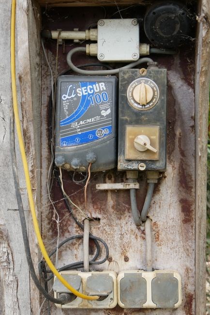
When a transfer switch fails, start by checking the breaker status, ensuring all connections are tight and free of corrosion. Verify the isolation switch is engaged, test the source with a multimeter, and review the wiring diagram for correct phase alignment.now
Common Faults and Diagnostics
In transfer switch installations, the most frequent problems arise from miswired connections, inadequate grounding, or phase mismatches. A common fault is the “back‑feed” condition, where the utility source is inadvertently energized through the transfer switch, endangering maintenance crews. Another frequent issue is the isolation switch failing to disengage, causing the backup source to overload the main panel. Over‑current protection can trip if the generator’s output exceeds the rated capacity of the transfer switch or if a short circuit occurs in the connected circuits. Ground‑fault detection often fails when the bonding jumper is loose or corroded, leading to a loss of reference voltage and potential shock hazards. Finally, many installations suffer from phase imbalance, where the three‑phase supply is not correctly matched to the generator’s phase sequence, resulting in uneven load distribution and possible equipment damage.
Diagnostics should begin with a visual inspection: check all wire colors, verify that the breaker is in the OFF position, and confirm that the isolation switch is fully disengaged. Use a multimeter to test continuity between the utility and generator buses, ensuring no unintended paths exist. Measure the voltage on each phase; a significant deviation from the nominal 120/240 V (or 208 V for three‑phase) indicates a phase mismatch. Inspect the grounding electrode system for corrosion or loose connections; a high resistance reading (>5 Ω) can mask a fault. Test the transfer switch’s internal relays with a signal generator to confirm proper operation under load. Finally, simulate a generator start‑up while monitoring the main panel’s current draw; any sudden spike beyond the rated amperage should trigger a diagnostic alarm.
After confirming all connections, perform a load test by running a 5 kW appliance and observing the transfer switch’s response. If the switch fails to engage, inspect the control relay for arcing or wear. Use a clamp meter to verify the current on each leg; values should remain within 10% of the generator’s rated output. If discrepancies persist, replace the transfer switch or consult the manufacturer’s fault code chart. Follow lock‑out tag‑out before work to ensure safety!

Quick Reference Wiring Table
| Component | Wire Color | Connection Point | Notes |
|---|---|---|---|
| Utility Bus | Blue/Black | Main Panel Bus Bars | Never connect to generator |
| Generator Bus | Red/Yellow | Generator Output Terminals | Must be isolated from utility |
| Transfer Switch Input | Blue/Black | Utility Bus | Feed through isolation switch |
| Transfer Switch Output | Red/Yellow | Generator Bus | Feed to main panel |
| Grounding Electrode | Green | Earth rod | Bond all metal parts |
| Isolation Switch | Yellow | Between Utility Bus and Transfer Input | Must be OFF during wiring |
| Control Relay | Black | Generator Control Panel | Ensure proper coil voltage |
| Load Breaker | Red | Main Panel | Match breaker rating to generator |
| Phase Indicator | White | Generator Output | Verify correct phase sequence |
| Safety Switch | Orange | Transfer Switch Housing | Lock‑out tag‑out required |
| S | S | Gen | S |
Use this table as a quick reference during installation. Verify each connection against the diagram before energizing the system. Keep this handy for future maintenance and troubleshooting
Resources and Further Reading
Below is a concise list of authoritative references and tools for mastering transfer switch wiring diagrams. These sources cover code requirements, manufacturer instructions, and practical tutorials.

- NEC 2024 – Codebook detailing all wiring, grounding, and safety rules.
- IEEE Std 142‑2023 – Grounding and bonding guidelines for generator interconnections.
- “Transfer Switch Wiring” by John D. Smith – Step‑by‑step diagrams and inspection checklists.
- NFPA 70E – Electrical safety standards for installation and maintenance.
- Manufacturer Manuals (Generac, Cummins, Briggs & Stratton) – Model‑specific wiring diagrams and clearance tables.
- UL 1741 Guide – Testing procedures and compliance criteria for standby generators.
- Udemy Course: “Backup Power Systems” – Video tutorials on theory and real‑world wiring.
- Electrical Engineering Stack Exchange – Community Q&A for troubleshooting.
- Manufacturer Webinars (Generac Live) – Live sessions on updates and best practices.
- PowerCAD – Open‑source software for custom wiring diagrams.
- Local Utility Interconnection Guides – Downloadable agreements and wiring instructions.
- State Building Code Portals – State amendments to the NEC and local ordinances.
Referencing these materials guarantees compliance, enhances safety, and supports reliable backup power solutions.
These references are essential for staying current with evolving standards, ensuring that installations meet safety regulations and operational reliability. By consulting the NEC, IEEE, and manufacturer manuals, installers can verify correct conductor sizes, grounding methods, and isolation procedures. Online courses and webinars provide visual demonstrations that reinforce theoretical knowledge, while community forums offer real‑world problem‑solving insights. Software tools like PowerCAD enable precise diagram creation and load simulation, reducing the risk of wiring errors. Local utility guides and state code portals further tailor the information to specific regional requirements, ensuring that every connection complies with both national and local mandates. Together, these resources form a comprehensive toolkit for any professional or knowledgeable DIYer seeking to design, wire, and maintain a safe, effective transfer switch system.